Reports
Can't get there from hereContents
| Title: | 4-way Radiometer Comparison 10-2016 | |||||||||||||||||||||||||||||||||||||||
| Date: | 2017-04-07 | |||||||||||||||||||||||||||||||||||||||
| Data File: | 4wayTest.csv | |||||||||||||||||||||||||||||||||||||||
| Refers to: | TW,2420,1720 | |||||||||||||||||||||||||||||||||||||||
|
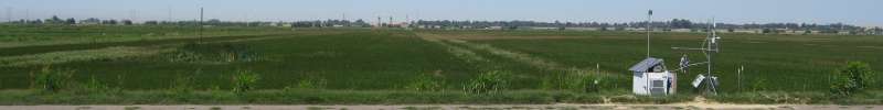
We compared two Huskeflux NR01 4-way radiometers. sn 1720 has some scratched SW domes; sn 2420 is a new instrument and the reference sensor. We want to determine updated calibration coefficients for sn 1720. Both sensors were deployed at the Twitchell Rice site from 2016-10-6 to 2016-10-20. From 2016-10-06 to 2016-10-11, the SWin and LWin domes were facing upward. From 2016-10-11 to 2016-10-20, the SWout and LWout domes were facing upward. We calibrated each component of 4-way radiation when its dome was facing upward: the upward-facing domes would have comparable views while the downward-facing domes would not necessarily have comparable views depending on the land surface below the domes. The raw output of the sensors is in mV. There is a factory calibration coefficient [uV/(W/m2)] that converts the mV reading to W/m2.  Updated calibration coefficients
  Figure 1. Time series for uncorrected SWin and SWout. Figure 2. Time series for corrected SWin and SWout. Figure 3. Time series for uncorrected LWin and LWout. Figure 4. Time series for corrected LWin and LWout. We use linear regressions to determine the new calibration coefficients for the test sensor, sn 1720.
Figure 5. Linear regression for SWin and SWout. The slope of this line converts to the updated calibration coefficient with units of (W/m2)/mV. Comparing LW_in and LW_out is more complicated because the relationship between mV and W/m2 depends on the calibration coefficient as well as the PRT temperature. LW [W/m2] = LW [mV] * Coef [(W/m2)/mV] + 5.67^10-8*T[K]^4 To compare the old and reference LWin and LWout, I wrote an iterative method in MATLAB for finding a calibration coefficient that would produce the best match between the old and reference sensors. I defined the best match between the two sensors as the calibration coefficient that gave a regression slope closest to 1 for a regression between the W/m2 values of the old and reference sensors. I assumed the corrected calibration coefficient would be between 70 and 90 [(W/m2)/mV]; LWin and LWout calibration coefficients for the reference sensor are 86.96 and 76.05, respectively. I created a vector that stepped between these two limits by 0.1. For each potential calibration coefficient, i.e., each possible case, the script generated the potential W/m2 output for the old sensor. It calculated the regression slope with each potential W/m2 output for the old sensor and each W/m2 output for the reference sensor. From all possible regression slopes, the script finds the one closest to 1. To check the new calibration coefficients, we plot the regression lines between the calibrated sn 1720 and sn 2420 have slopes close to 1 and offsets close to 0.
Figure 6. Linear regression for corrected LWin and LWout to check the new coefficients. Figure 7. Time series of PRT temperatures. Â |
||||||||||||||||||||||||||||||||||||||||
| |